Hero Image

Battery System Installation & Start-Up: A Clear, Practical Guide

Mr. Kasiean Sukemoke

Mr. Kasiean Sukemoke

Founder & MD

August 27, 2025 at 07:28 AM# VRLA# Battery Installation# Electrical Safety# UPS# Commissioning

PDF Content


PDF Summary

1) Safety First: Core Hazards and Controls

1.1 Electrical Shock & Short-Circuit

  • Remove all metallic personal items (rings, watches) before working.*
  • Use insulated tools and wear rubber gloves.*
  • Never connect/disconnect under load; isolate sources before touching terminations.*
  • Before placing batteries on racks/cabinets, measure voltage from battery terminals to rack/cabinet frame—this should read 0 V (no leakage to chassis).*

1.2 Chemical Exposure (Acid/Gel Electrolyte)

  • Electrolyte (gel or liquid acid) is corrosive and conductive; it can burn skin and eyes.*
  • If skin contact occurs: rinse immediately with water. If in eyes: use eye-wash solution or clean water and seek medical care.*
  • Neutralize spills with sodium bicarbonate (≈ 1 lb per 1 gallon water).*

1.3 Fire, Explosion & Heat (Hydrogen Management)

  • Lead-acid batteries can emit hydrogen during overcharge; eliminate ignition sources—no smoking/sparks nearby.*
  • Do not charge in sealed cabinets/rooms. Provide ventilation and 0.5 in (≈1.25 cm) spacing between units for heat dissipation.*
  • Ensure the room has adequate airflow to prevent hydrogen accumulation.*

2) Tools & Equipment Checklist

General tools

  • Digital voltmeter.
  • Insulated open-end spanners.
  • Torque-adjustable wrench.
  • Forklift or suitable lifting aid (batteries are 10–35 kg each).*
  • Rubber gloves, face shield, apron, eye-wash solution, fire extinguisher.*

Optional/diagnostic

  • Micro-ohmmeter or internal resistance/conductance tester.
  • Battery resistance test set.
  • 100 A load test kit.
  • DC load (or AC load for UPS acceptance tests).*

3) Pre-Installation Preparation

  1. Define string topology (series / parallel per system voltage). See examples below.*
  2. Plan intercell, inter-row, and inter-rack connections and terminations.*
  3. Prepare racks/cabinets and cable routes; confirm ventilation and service clearances.*
  4. Inbound inspection: check for physical damage; verify that hardware (bolts, washers, terminal covers) is complete.*
  5. Staging & logistics: use a temporary warehouse/staging area for pre-checks and transport readiness.*
  6. Leakage & isolation checks: measure voltage
    • between rows,
    • between tiers,
    • between racks/cabinets,
    • and from each battery terminal to rack/cabinet structure (should be 0 V).*
  7. Record all pre-install measurements on commissioning sheets (baseline for warranty/maintenance).*

4) Installation Sequence (Task Flow)

  1. Place batteries into racks from bottom to top to maintain stability and safety.*
  2. Maintain 0.5 in (≈1.25 cm) spacing for interconnect clearance and cooling.*
  3. Uniform polarity orientation across the rack: all positives aligned in the same direction; same for negatives—prevents wiring mistakes.*
  4. Clean terminals with a soft brass brush to remove oxidation that may have formed during transport.*
  5. After torquing connections to specification, apply antioxidant grease (e.g., No-Ox-ID or NCP-2) at the contact surfaces to mitigate future oxidation.*
  6. Do not use lubricants on racks/cabinets—hydrocarbons can degrade plastic battery cases over time.*
  7. Number the batteries in drawings and on physical labels for easy maintenance tracing. Keep cable sizes consistent across series/parallel paths to preserve voltage balance.*

5) System Topologies (Examples)

  • 360 VDC system: e.g., one three-tier rack with 30 × 12 V VRLA batteries connected in series.*
  • 480 VDC system: e.g., two three-tier racks with 40 × 12 V VRLA batteries connected in series.*

Always confirm the required number of series cells:
If ( N ) batteries of nominal ( V_{\text{bat}} ) are in series, the nominal string voltage is
$$V_{\text{string}} \approx N \times V_{\text{bat}}.$$


6) Storage Guidelines (Pre-Commissioning)

  • Store in a clean, dry, cool (≈ 25 °C) room away from heat sources (sunlight, condenser coils, etc.).*
  • Avoid temperature swings—these increase self-discharge and shorten the allowable storage interval before a freshening charge is needed.*

7) Freshening Charge (Initial Recharge Before Service)

Use a freshening (boost) charge if:

  • Any 2 V cell measures < 2.07 V, or a 12 V monobloc measures < 12.4 V (open-circuit).*

Charging set-points

  • Charge at 2.40 V per cell (for a 12 V monobloc with 6 cells: (6 \times 2.40 = 14.40) V).*
  • Duration: ~24 hours at 25 °C; perform every 6 months during storage if needed.*
  • Current limiting: limit charge current per the manual’s guidance relative to the 20-hour rated discharge current.*

Inline formula reminder: Float/boost voltages scale with temperature in detailed specs; consult the individual battery datasheet for temperature compensation.**


8) Post-Install Acceptance

  • Re-measure:
    • Inter-row, inter-tier, inter-rack potentials.
    • Terminal-to-rack potentials (should be 0 V).
  • Verify torque on all intercell and bus connections.
  • Document string voltages and individual unit voltages; retain as commissioning baseline.
  • Where applicable, perform impedance/conductance tests and acceptance/capacity tests (or UPS load tests) per site procedures.*

Conclusion

A safe, reliable VRLA installation hinges on disciplined preparation, strict hazard controls, correct mechanical/electrical assembly, and a documented freshening charge. Consistent labeling, spacing, torqueing, and baseline measurements set you up for easier maintenance and longer service life.*

All of Our Knowledges

Fallback Logo
Capacity Testing of VRLA Batteries: A Clear, Practical Guide

Capacity testing verifies whether a valve-regulated lead–acid (VRLA) battery bank can still deliver the current or power promised by its manufacturer over a specified time at a defined end-of-discharge voltage and temperature. This guide turns the technical procedure into a step-by-step checklist you can use in the field, with simple math to calculate the **Rated Capacity (%)** and account for temperature.

Fallback Logo
Thermal Runaway in Lead-Acid Batteries: Causes, Risks, and Practical Prevention

Thermal runaway is a dangerous feedback phenomenon in battery systems where rising temperature drives higher charging current, which in turn generates more heat—potentially leading to swelling, venting, or even fire.* This article explains the mechanism in plain language and distills field-ready practices to prevent it.

Lead-Acid Battery Fundamentals: How They Work, Types, and Lifespan

A complete guide to the fundamentals of lead-acid batteries. Learn about their working principles, structure, classifications (Flooded, VRLA, AGM, Gel), and the key factors like temperature and discharge that affect capacity and lifespan.
Battery Showdown: Lithium-ion vs. Advanced Lead Carbon VRLA for Stationary Applications

As the world increasingly relies on renewable energy and robust power grids, the demand for effective stationary energy storage solutions has surged. Two leading technologies dominate this space: Lithium-ion (LiB) and Advanced Lead Carbon VRLA (Valve-Regulated Lead-Acid) batteries. While Lithium-ion is known for its high performance and energy density, Advanced Lead Carbon offers a reliable and cost-effective alternative. This article provides a comprehensive comparison of these two battery types across technical specifications, safety, economics, and application suitability to help determine the best choice for various stationary uses.
Dynasty VRLA Battery System: Maintenance and Troubleshooting Guide

Valve-Regulated Lead-Acid (VRLA) batteries are widely used in backup power systems due to their sealed design and low maintenance requirements. However, to ensure reliable performance and long service life, regular inspection and systematic maintenance are essential. This guide summarizes the **periodic maintenance steps**, **troubleshooting methods**, and **best practices** for Dynasty VRLA battery systems.
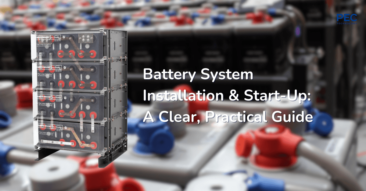
Battery System Installation & Start-Up: A Clear, Practical Guide

This guide distills the uploaded “Battery System Installation and Start-Up Instructions” into a concise, field-ready article. It focuses on safety, preparation, installation sequencing, initial charging (“freshening charge”), and post-install checks for VRLA (valve-regulated lead–acid) battery systems.*

Why Lead-Acid Batteries Fail — Practical Causes, Diagnostics, and Prevention

Lead-acid batteries (flooded and VRLA/AGM/Gel) usually fail for predictable, preventable reasons. This article organizes the common failure modes, explains the electrochemistry in plain language, and outlines field diagnostics and maintenance practices to extend service life.

Fallback Logo
Choosing and Using VRLA Batteries (AGM vs. Gel): A Practical Guide

Valve Regulated Lead-Acid (VRLA) batteries are widely used in critical power systems because they’re sealed, low-maintenance, and safe when operated correctly. This guide explains how VRLA batteries work, compares Absorbent Glass Mat (AGM) and Gel technologies, and gives clear, field-ready advice for selecting the right type and operating it for long life.

Ready to Upgrade Your Power Infrastructure?

Connect with PEC Technology Today!

Secure reliable power. Minimize downtime. Future‑proof your systems.

Menu